Combinational Circuits
Any circuit is divided into two parts :
Combinational Circuits
Sequential Circuits
Combinational Circuits :
Combinational circuits are fundamental digital logic building blocks where the outputs are purely determined by the current input values at any given moment. Unlike their sequential counterparts, these circuits have no memory of past events - they respond instantaneously to input changes, much like a light switch that immediately illuminates a room when flipped.
Think of combinational circuits as digital truth machines - they evaluate logical relationships and produce consistent, predictable results. Just as a calculator always gives you the same answer for 2+3, a combinational circuit will always produce identical outputs for identical inputs, regardless of when or how many times you apply those inputs.
Fundamental Characteristics:
Memoryless Operation: Outputs respond instantaneously to input changes without retaining any information about previous states. The circuit has complete "amnesia" about its history.
Unidirectional Information Flow: Data travels in a single direction from inputs to outputs, with no feedback paths that could create loops or oscillations. This ensures stable, predictable behavior.
Asynchronous Response: Unlike sequential circuits that wait for clock edges, combinational circuits operate continuously and respond immediately to input transitions, limited only by the physical propagation delays of the gates.
Deterministic Behavior: The circuit acts as a pure function - the same input combination will always produce the same output combination, making analysis and verification straightforward.
Half Adder
Real-Life Context: The Foundation of Digital Arithmetic
Imagine you're designing a simple digital thermometer that needs to add temperature readings from two sensors. The half adder is like having a basic adding machine that can handle the simplest case - adding two single-digit binary numbers.
Real-World Example: Digital Voting System In electronic voting machines, when counting "Yes" and "No" votes from two districts, a half adder circuit can determine if there's an overall majority and whether there's a tie that needs to be escalated to the next level.
Theory
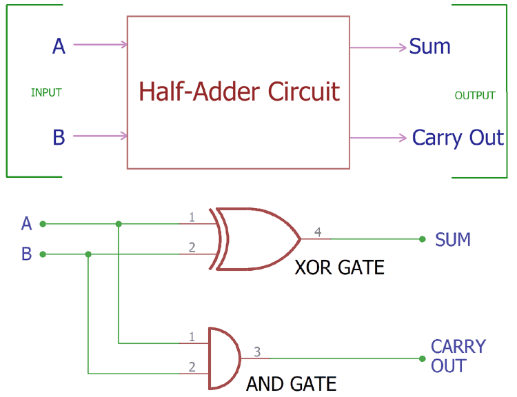
A half adder is the most basic arithmetic building block in digital systems. It performs addition of two single binary digits, producing a sum and a carry output. It's called "half" because it handles only two inputs without considering any carry from previous operations.
Truth Table
A B S C
0 0 0 0
0 1 1 0
1 0 1 0
1 1 0 0
where S = Sum, C = Carry
Real-world interpretation:
A=0, B=0: No votes from either district → No majority, no escalation
A=0, B=1: One vote → Majority decided, no escalation needed
A=1, B=0: One vote → Majority decided, no escalation needed
A=1, B=1: Both districts vote → Tie situation, escalate to higher authority
Boolean Expressions
Sum (S) = A ⊕ B (XOR operation)
Carry (C) = A · B (AND operation)
Full Adder
Theory
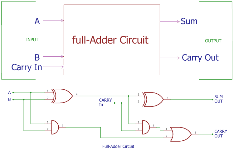
A full adder is a combinational circuit that adds three binary inputs: two significant bits (A and B) and a carry input (Cin) from a previous stage. It produces a Sum (S) and Carry output (Cout).
Truth Table
Input | Output | |||
A | B | Cin | Sum | Cout |
0 | 0 | 0 | 0 | 0 |
0 | 0 | 1 | 1 | 0 |
0 | 1 | 0 | 1 | 0 |
0 | 1 | 1 | 0 | 1 |
1 | 0 | 0 | 1 | 0 |
1 | 0 | 1 | 0 | 1 |
1 | 1 | 0 | 0 | 1 |
1 | 1 | 1 | 1 | 1 |
Boolean Expressions
Sum (S) = A ⊕ B ⊕ Cin
Carry (Cout) = AB + Cin(A ⊕ B) = AB + ACin + BCin
It can be implemented in below ways :
Implementation Methods
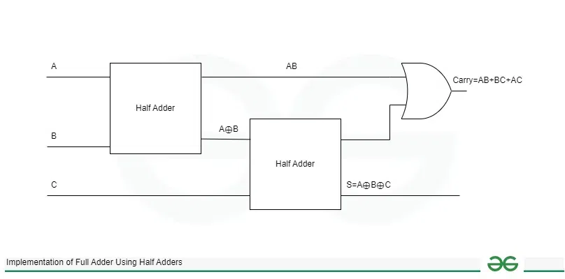
Using two half adders and one OR gate
Direct gate implementation using XOR, AND, and OR gates
Using NAND gates only (9 NAND gates required)
Full Adder using Half Adder :